
http://player.youku.com/player.php/sid/XNzA5NDg0MzIw/v.swf
A maze designed for Katyusha[Катюша].
Katyusha is a cute hamster lives in Shanghai. She's very smart, a bit aggressive, but a quite adorable young lady in general. She loves sunflower seeds and littleBits.
Northy upload this instruction to littlebits -> https://littlebits.cc/projects/hamster-maze
Bits used: bargraph , bright led, dc motor , double AND, double OR, fork, inverter, light sensor, light trigger, NAND, power , pressure sensor, slide switch, sound trigger, split, vibration motor, wire

Instructions
- Design your maze, make sure there’s only one way to get in and get out.
- Cut foam core follow the maze map to build up the walls. Adjust the design of the maze after your pet runs several rounds for test to see if the path is working.
- Paper fold some platonic solids and paste them onto the places of the maze as blocking obstacles. You can choose some to have vibration motor hidden inside, and then embed sound trigger to the back of the maze. Use the littleBits screwdriver to adjust the sound trigger to make sure the hamster’s footsteps will trigger the vibration motors.
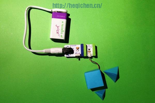
- At the center of the maze, there is a three- direction-crossing stage for the hamster to choose, and only one of them is the right path. To visually make the statement even stronger, I added an optical illusion underneath the transparent acrylic stage. Print the graphic and attach it to the DC motor with the littleBits motorMate.
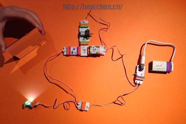
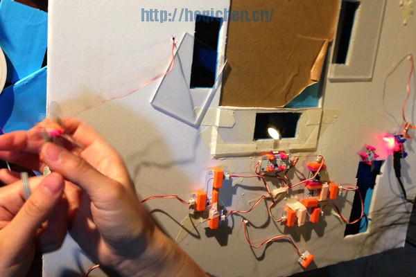
- The idea for the stage is once the hamster chooses the path correctly, she would stop the rotating stage and triggers the BINGO signal on the exit wall of the path. To create that, you need to set up a loop circuit with logic bits NAND+ AND and two inverter bits. The idea is when the pressure sensor embedded under the right path is pressed by the hamster, the inverter bit will send the “false” signal to the NAND bit, which will send out the “true” signal to the connected AND bit, and the other gate of the AND is a turned on slide switch. So the AND comes to be “true” which triggers the bargraph bit behind the BINGO cut out, and projects the words BINGO onto the inner wall. The inverter bit after the AND inverts the “true” signal to “false” and stops the DC motor rotating the optical illusion graphic. The circuit goes back to the other gate of NAND as a “false” signal to always triggers the NAND bit. So the circuit becomes a loop. No matter how many times the hamster steps on the pressure sensor again, once the circuit is triggered, the stopped stage and the lighted up “BINGO” should lead smart Katyusha to the right way. Please take a look of the first orange logic circuit pic in the gallery and set up the same circuit to play around for better understanding. (The photo includes several bright leds only for the true/false signal display.)
- Cut out three rectangular foam core pieces to embed the three pressure sensors. Connect bright leds after the pressure sensors individually and embed them to back of the cut out ”NO” walls for word projection.
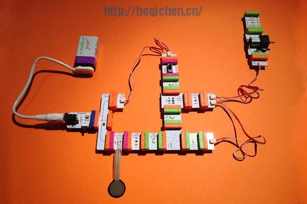
- After the rotating stage, Katyusha will run into a road ends up with a mirror. The idea is before Katyusha’s arrival, there is a bright led on the back wall of the road, which reflects to the mirror on the other end of the road and triggers off the light trigger which was switched to “dark”. Once she gets onto the road, she blocks the bright led light to the mirror and triggers the light trigger to send the “true” signal to one gate of the OR bit so that the OR will send out “true” signal to turn on the DC motor of the running machine and turns on the bright led connected at the end of the circuit which is also physically flipped on the top of another light trigger to the other OR gate for always sending out the “true” signal and loop this OR circuit. This means once the hamster arrives on the road and blocks the light, the running machine will be triggered on immediately and forever. Please take a look of the second orange logic circuit for your reference.
Bits used (28)
- bargraph x 1
- bright led x 2
- dc motor x 2
- double AND x 1
- double OR x 1
- fork x 1
- inverter x 2
- light sensor x 1
- light trigger x 1
- NAND x 1
- power x 2
- pressure sensor x 3
- slide switch x 1
- sound trigger x 1
- split x 1
- vibration motor x 2
- wire x 5
Other Materials Used (7)
- acrylic x 1
- construction paper x 1
- double sided tape x 1
- foam core x 1
- plastic gear x 2
- styrofoam x 1
- tape x 1
Tools (2)
- scissors
- x-acto
3,111 total views, 2 views today
